“The power grid is a physical network that every household uses, and the basic function of existing power lines is to transmit electricity. Using the existing power lines to realize data communication without adding additional communication lines can greatly save the construction cost. The intelligent system introduced in this paper only needs to embed the communication Modules and power supply Circuits of different functions in the system into the wall like wall sockets and connect to the mains to realize the intelligent home system.
“
The power grid is a physical network that every household uses, and the basic function of existing power lines is to transmit electricity. Using the existing power lines to realize data communication without adding additional communication lines can greatly save the construction cost. The intelligent system introduced in this paper only needs to embed the communication modules and power supply circuits of different functions in the system into the wall like wall sockets and connect to the mains to realize the intelligent home system.
1 Overall system design
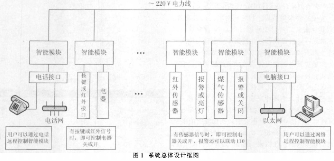
The overall design block diagram of the system is shown in Figure 1.

The whole system is composed of different intelligent modules. The intelligent module is composed of power supply Circuit, SC1128 transceiver circuit and peripheral circuit. Each intelligent module corresponds to a different address to avoid executing commands that do not belong to this module. The address can be set by a custom IR remote.
2 Intelligent module hardware circuit
The hardware circuit is divided into three parts: power supply, SC1128 transceiver circuit, peripheral circuit and functional circuit.
2.1 Power Hardware
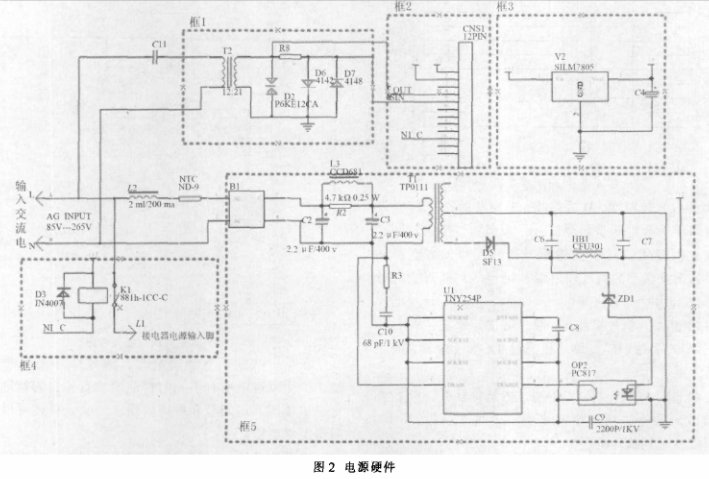
The schematic diagram of the power supply hardware module is shown in Figure 2. The functions of each module are as follows:

(1) Box 1 is a coupling circuit. The coupling circuit is the output and input path of the carrier signal, and has the function of isolating the 220 V/50 Hz power frequency. When designing this circuit, the impedance characteristics of the 220 V line side should be considered. T1 is a signal coupling transformer, and the impedance of the 220 V line side is generally 3 Ω to 30 Ω. Then determine the turns ratio or impedance ratio of the primary coil to the primary. Design the output matching resistor of the power amplifier. The input channel is connected to a surge protection diode, which is isolated by a resistor and then connected to a diode clamp circuit to output to the front-end filter circuit.
(2) Box 2 is the interface between the power supply and the communication module. SC1128 communicates with other intelligent modules through POUT (send) and SIN (receive) 2 pins. This allows one smart module to control another smart module.
(3) Box 3 stabilizes +12 V to +5 V to supply power to the system.
(5) Box 5 obtains +12 V power supply through rectification.
2.2 SC1128 transceiver circuit and peripheral circuits
The circuit of the hardware system is the transceiver circuit of SC1128.
(1) SC1128 transmission and reception circuit through power line

The SC1128 chip is a dedicated spread spectrum modulation/demodulator circuit developed for the power line carrier communication market. Due to the adoption of new technologies such as direct sequence spread spectrum, digital signal processing, and direct digital frequency synthesis, the circuit has strong anti-interference and anti-attenuation performance in power line communication. The SC1128 chip integrates spread spectrum/despread, modulation/demodulation, D/A and A/D conversion, built-in Electronic meter, output driver, input signal amplification, watchdog, working voltage detection and serial port with microcontroller (MCU). communication and other functions. The chip can reduce system cost and improve system function in small multifunctional application system.
The diagram of SC1128 sending and receiving through the power line is shown in Figure 3.
The coupling circuit can couple the signal transmitted by the power amplifier to the power line; and can couple the signal received on the power line to the band-pass filter. The band-pass filter and the pre-amplifier are the pre-stage receiving channel, which amplifies and filters the received signal and sends it to the operational amplifier of the SC1128 for processing. The power amplifier amplifies the phase modulation signal sent by SC1128, and sends it into the power line through the coupling coil.
(2) Connection circuit between SC1128 and microcontroller
The single-chip microcomputer selects the STC89C58RD+ with super strong anti-interference/high speed/low power consumption introduced by Hongjing Technology. This single-chip microcomputer comes with 32 KB Flash and 1280 B RAM inside, which can avoid external expansion of EEPROM. In particular, the single-chip microcomputer supports online programming, which brings convenience for future software upgrades.
SC1128 is connected with the microcontroller as shown.
Pin 36 is the transceiver control terminal, 0 is for reception, 1 is for transmission; Pin 37 generates a synchronization pulse signal after the transmission and reception are synchronized, and the frequency changes with the change of the working master clock and cycle; Pin 38 is for outputting the data sent and received; Pin 39 is the input and output terminal for setting data and status; Pin 40 is the input terminal for synchronously setting the clock; Pin 41 is the input terminal for chip selection.
In the transmitting state, the single-chip microcomputer sets the SR terminal (pin 36) high, the SC1128 chip sends a synchronization header (pin 37), and the single-chip microcomputer sends data synchronously through the TX terminal (pin 38).
In the receiving state, the single-chip microcomputer sets the SR terminal (pin 36) low. If the SC1128 chip receives data, it will generate a synchronization header, and send the data to the single-chip microcomputer synchronously through the TX terminal (pin 38).
During normal operation, the 36th pin (SR) of SC1128 is always set to 0 when not transmitting, and is in a waiting state.
2.3 Functional circuit
The functional circuit is a circuit added according to the different functions to be realized, including:
(1) Button circuit: control the relay through the button to achieve the function of controlling electrical appliances;
(2) Voice circuit: can realize remote telephone control of electrical appliances;
(3) Sensor circuit: Select the sensor according to the needs, such as infrared sensor. When someone passes by, the sensor sends a signal to the microcontroller to control the relay. The relay here can be connected to a light or an alarm module. Gas sensor can detect gas leakage and alarm;
(4) Computer interface circuit: it can be controlled remotely through the network, or it can Display the status of electrical appliances or control each electrical appliance in the computer;
(5) LCD interface circuit: it can display the status of each electrical appliance;
(6) Remote control circuit: Simply put, it is possible to learn the remote control codes of all remote control appliances in a room, so that a custom remote control can be used to remotely control all the appliances.
3 Intelligent module software part
The main flow chart of the single-chip software design is shown in Figure 5.
When using the smart module for the first time, set the address through the infrared remote control. All the different smart modules in a home have their own addresses, which can be defined by floor, room number and appliances used. The specific can be determined according to the actual situation.
The system has been proved by long-term test operation that it has the characteristics of small maintenance, low error code and strong anti-interference ability. The spread spectrum system requires only a small space, does not need to add additional wiring, and has a short construction period, which greatly improves and facilitates people’s quality of life, and improves the security capability of the family.
The Links: 7MBP150RA120 6MBI15S-120-02