“In order to more efficiently complete the test and verification of the lane departure warning system function of the vehicle-mounted front-view camera, a simulation test program of the vehicle-mounted camera in the loop is proposed. Integrate a mass-produced vehicle-mounted camera into a hardware-in-the-loop real-time simulation system and communicate in real-time through CAN channels. Use scene modeling software to realize the construction of different road, weather, visibility and other simulation conditions, and then use automated testing software to perform global test cases The configuration to detect the performance of the camera lane departure warning system.
“
In order to more efficiently complete the test and verification of the lane departure warning system function of the vehicle-mounted front-view camera, a simulation test program of the vehicle-mounted camera in the loop is proposed. Integrate a mass-produced vehicle-mounted camera into a hardware-in-the-loop real-time simulation system and communicate in real-time through CAN channels. Use scene modeling software to realize the construction of different road, weather, visibility and other simulation conditions, and then use automated testing software to perform global test cases The configuration to detect the performance of the camera lane departure warning system.
The results show that the simulation test method can better realize the functional logic and performance test of the camera, and the performance of the camera varies greatly under different working conditions, which provides a reference for the optimization of the camera’s lane departure warning system and the actual vehicle test in the later period.
Advanced driving assistance system (ADAS) is an important part of automobile intelligence, including forward collision warning (FCW), adaptive cruise (ACC), lane departure warning system (LDW), etc., which are improving driving safety and alleviating traffic congestion. This aspect has important practical significance.
Among them, the lane departure early warning system mainly relies on the vehicle-mounted visual sensor to complete the detection of the lane line. When the driver has an unconscious departure behavior, the driver’s attention is drawn through an alarm to ensure the safety of the vehicle.
For the test verification of the lane departure warning system function, most of them are completed through controlled field tests, but there are disadvantages such as high labor and material costs, cumbersome test procedures, and high vehicle control requirements, especially in some special scenes that are difficult to reproduce repeatedly. .
The hardware-in-the-loop test method, as an important part of the in-the-loop test, realizes the effective connection of model-in-the-loop, software-in-the-loop and vehicle-in-the-loop in the V-shaped development process of vehicle ADAS function. The application of various in-the-loop test methods in the V-shaped development process also makes the vehicle ADAS function development and verification more systematic and efficient. Researchers at home and abroad have done a lot of research on related aspects.
This paper proposes a simulation test method for vehicle-mounted camera lane departure warning system based on the NI real-time simulation system. By building a hardware-in-the-loop simulation platform including video black box, CAN communication, etc., it has completed the test of a certain mass-produced vehicle-mounted camera lane. Deviate from the simulation test verification work of the early warning system’s functional logic and performance parameters, find out the shortcomings of the camera, and make its later optimization and improvement more targeted.
01. Camera-in-the-loop test system construction
In order to complete the simulation test research of the vehicle-mounted camera lane departure warning system, this paper builds a camera-in-the-loop simulation test system, which is mainly composed of the NI PXI real-time simulation system, high-precision vehicle dynamics model, high-fidelity scene model, camera to be tested, video The black box, CAN signal module, programmable power supply and automated test software are composed. The system block diagram is shown in Figure 1.

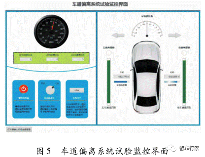
Veristand is a software environment developed by the NI company for the PXI real-time simulation test system. It is used to configure the input and output of the relevant boards, deploy the vehicle dynamics model, and complete the mapping and connection of the relevant parameter interfaces. The lane departure system monitoring interface is designed through the software to monitor the relevant state parameters of the test vehicle in real time.
The high-precision dynamics model runs in the PXI real-time simulation system to reproduce the dynamic characteristics of the simulated vehicle in real time. The test environment model is mainly built by high-fidelity scene modeling software, which can freely configure weather, visibility and other environmental factors and simulate different traffic conditions, complete the reproduction of certain dangerous or difficult to repeat test scenes, and the relevant environment model is displayed through the visual scene The device serves as the capture input of the camera.
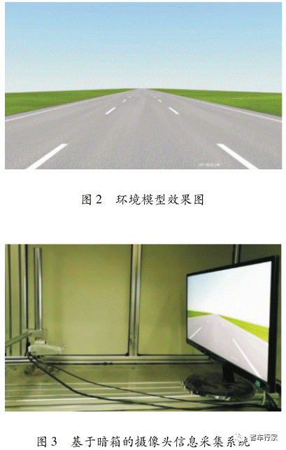
In order to better meet the requirements of the test procedures and avoid interference from other objects on both sides of the road, the basic environmental effects are shown in Figure 2. The camera acquisition part includes the camera to be tested, the visual Display and the black box. The collection of lane information is shown in Figure 3; the programmable power supply provides power support for powering on and off the camera; automated test cases and process configuration are mainly realized through automated test software, combined with CAN signal analysis tools to complete lane line recognition and lane The extraction and analysis of deviation warning signals.
During the test, the vehicle speed information is sent from the high-precision dynamics model to the camera through the CAN channel to activate the lane departure system. The camera under test in the dark box takes real-time images of the scene displayed by the environment model and completes the collection of lane line information. As shown in Figure 4, the environmental conditions and lane line recognition can be visually monitored. If the lane line is detected and there is no alarm, the detected lane line is green, and the alarm is red.

At the same time, the lane recognition information or departure warning information is sent to the monitoring interface of the lane departure warning system designed by Veristand to control the power supply of the camera, the ignition of the engine and the switch of the LDW system, and monitor the speed, heading angle, and distance of the vehicle from the lane line. Information such as whether it has alarmed or not is convenient for real-time understanding of the working status of the vehicle and the LDW system, as shown in Figure 5.
The automated test software deploys environmental model parameters according to the written test cases and monitors the status information of vehicles and cameras in real time, so as to realize the switching of different test procedures and the judgment of test results.
02. Test and test process design
When testing a mass-produced camera with a lane departure warning system, it is important to pay attention to the stability and accuracy of its lane recognition and departure warning. You can refer to the China Automotive Engineering Research Institute Co., Ltd. (abbreviated as China Automotive Research Institute) National Smart Car Standard performance test is carried out in the “Lane Departure Early Warning System Test Regulations” issued by the Integrated System Test Area (i-VISTA).
At the same time, the functional logic test is completed with reference to its function definition, and environmental models under different weather, road area, water, and visibility are further designed to achieve a more in-depth environmental adaptability test. Finally, with the help of automated testing software, the designed performance test, functional logic test and environmental adaptability test are completed in turn quickly and efficiently.
2.1 Performance test
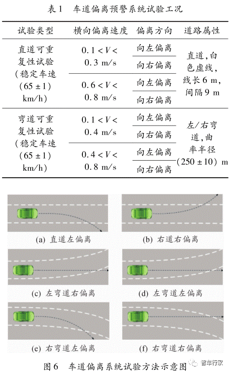
The performance test is an important test in the China Smart Car Index System issued by China Automotive Research Institute for Smart Connected Cars. This article refers to the “Lane Departure Warning System Test Regulations” in the system to test the camera under test to verify its basic performance under standard conditions. The design test conditions of the test procedure are shown in Table 1, and the schematic diagram of the lane departure test method is shown in Fig. 6.
2. 2 Functional logic test
The functional logic test focuses on the logic state of the camera, and detects whether it can realize the conversion of different states of the LDW system under the required conditions. The state transition logic is shown in Figure 7.

In this experiment, the programmable power module is used to power the camera, and the test cases for the various state power supply conditions in the system state logic diagram are designed through the analog signal board of the real-time system, and the power switch, engine ignition switch, and LDW are respectively set and controlled. Parameters such as system switch and vehicle speed are used to verify whether the state logic switch is reasonable.
It mainly tests the three logic conversions of camera power on and off, system on/off, and system activation/exit. The specific test conditions are shown in Table 2.

2. 3 Environmental adaptability test
During the performance test, the weather conditions were good, and the basic functions of the camera were tested for typical working conditions. The environmental adaptability test focuses on the accuracy and stability of camera lane recognition and departure warning in different weather environments.
In the environmental adaptability test, the road structure, lane line specifications, and deviation speed are consistent with the performance test. Different weather environment models are mainly added to simulate the rain, snow, and fog weather conditions that are difficult to reproducibly verify in the actual vehicle test to detect them. The recognition rate and different weather environment models are shown in Figure 8.
2. 4 Automated test case design
For the camera lane departure warning system to test different working conditions, on the one hand, it is necessary to take into account the testing and monitoring of different working conditions, on the other hand, it is necessary to improve the test efficiency on the basis of ensuring the accuracy of the test. This paper uses automated testing software to compile test procedures and evaluation standards for different test conditions to improve its test efficiency.
In the test process, the automated test software calls the environmental models of different test conditions in turn according to the prepared test cases. The camera signals and vehicle status information in the NI real-time simulation system are also connected to the software to realize real-time monitoring of relevant parameter information. And judge whether it passes the test standard requirements.

The automated test case design is shown in Figure 9. Take the left-curve high-speed left-deviation operating condition as an example. The beginning part of the test is mainly to load the vehicle dynamics model and the simulation environment model, and start to record related parameters; the camera parameter settings are mainly to benchmark the installation position and angle of view of the camera; the environment; Parameter settings mainly control the weather and road conditions of the environmental model;
Then obtain the status signal of the camera ECU according to the CAN message output by the camera, and judge whether the LDW system is normally activated; if the system is normally activated, it will enter the alarm signal monitoring, and judge whether an alarm signal is generated when the lane deviates from the CAN message signal;
After detecting the alarm signal, proceed to the next step immediately, read the lateral deviation speed of the vehicle to determine whether it is within the specified speed range, and finally terminate the operating condition and automatically enter the next operating condition for testing. In this way, global test cases are designed, covering basic functional logic tests, performance tests, and environmental adaptability tests, and the required test reports are generated to realize the automated test of the lane departure warning system.

03. Test results and analysis
3.1 Performance test
In the performance test, each test condition was tested 4 times, and the straight track repeatability test was performed 16 times. The test results are shown in Table 3.
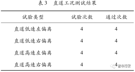
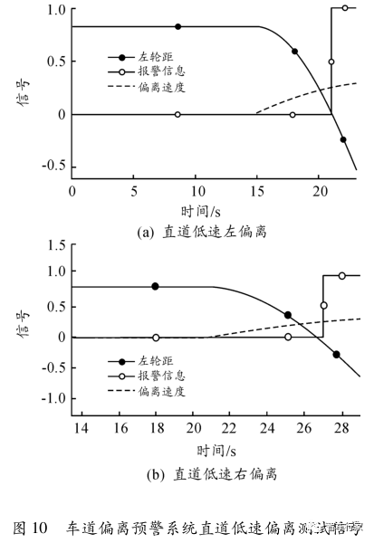
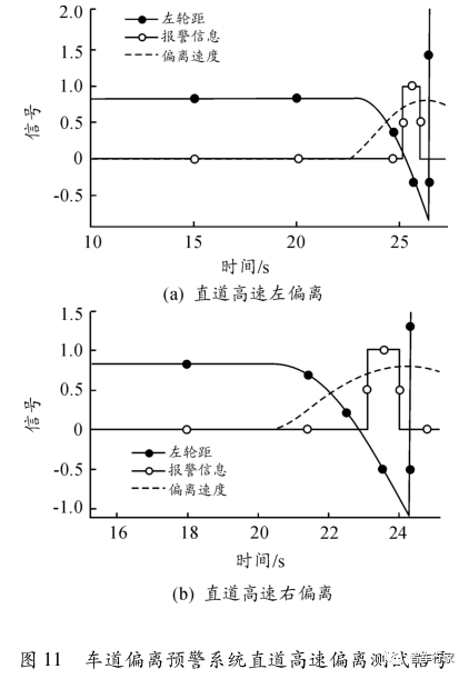
In the test, the straight-line low-speed and high-speed deviation conditions all passed normally. The results are shown in Figures 10 and 11, when the wheel track is at -0. 1~0. In the range of 1 m, an alarm signal can be generated in time.
When conducting the left deviation test, focus on the distance between the left wheel and the left lane line and whether there is an alarm signal within the specified distance. If an alarm signal is generated, verify whether the lateral deviation speed is within the specified speed range. When deviating to the right The focus is on the distance between the right wheel and the lane line on the right, and information such as the warning signal, the lateral deviation speed and the wheel distance at the time of the warning are monitored at the same time.
The vertical axis in the figure is the signal axis, and the dimension is not indicated.
The values can be used for the alarm signal, the track and the lateral speed at the time of deviation. The alarm signal is a 0-1 signal, the track unit is m, the deviation speed unit is m/s, and the absolute value is taken. Other signal diagrams in this section are the same.
The curve repeatability test was carried out 32 times in total, and the test results are shown in Table 4.
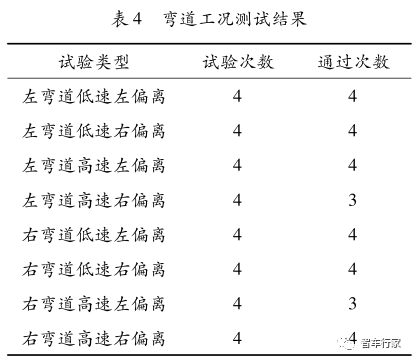
All low-speed left/right deviation conditions can be passed without specific analysis. In the high-speed deviation condition, the camera recognition effect is not good when the left-curve and the right-curve deviate to the left and the right-curve deviates to the left. The alarm failed in time in 1 of the 4 tests. The test signals of the lane departure system are shown in Figures 12 and 13.
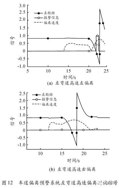
Figure 12(a) shows the high-speed left-deviation operating condition of the left corner, and the alarm is normal when the left track is about 0. Figure 12(b) shows the high-speed right-departure condition of a left corner. When the vehicle deviates from the right side, the lane line recognition is unstable, which causes it to fail to alarm normally. Figure 13(a) shows the high-speed right deviation condition of the right corner, and the alarm is normally issued when the right track is approximately equal to zero.
Figure 13(b) shows the high-speed left-deviation condition of the right corner, and the same situation as the high-speed right deviation of the left corner occurs. From the real-time image of the camera, when the vehicle shifts in the two unalarmed conditions, the relative movement causes the arc of the curve lane line to quickly deviate to the side of the vehicle, and the recognition effect is poor and unstable.

Through the performance test, the basic performance results of the camera under test in typical working conditions were verified and analyzed. Among them, in straight road conditions, the road structure is simple, and lane lines can be effectively identified and promptly warned when they deviate; in curved road conditions, lane line recognition is unstable, especially in left-curve high-speed right deviation and right-curve high-speed left In the two high-speed reverse deviation conditions, the alarm cannot be reported in time, which provides a basis for later real vehicle verification and camera algorithm optimization, and improves the efficiency of product development and testing.
3. 2 Functional logic test
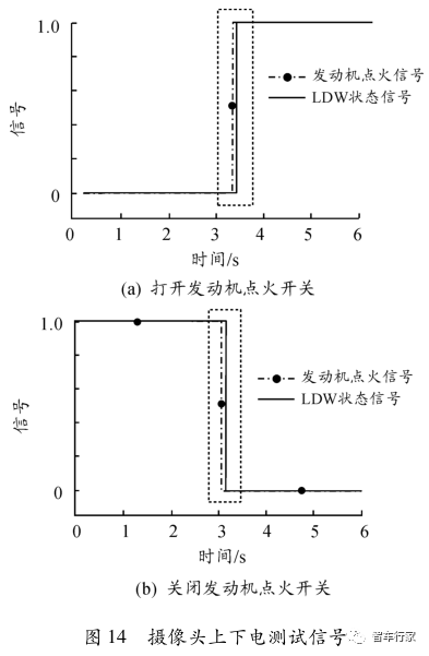
When the camera is powered on and off, the battery power supply and the LDW system switch are in the on state, the vehicle is stationary, and the ignition signal of the engine is controlled to open and close to detect the state of the LDW system. As shown in the dashed box in Figure 14, the engine ignition signal is set to on in (a), and the LDW system state changes to 1, that is, the standby state; when the engine ignition signal is set to off in (b), the LDW system state changes to 0, that is Disconnected state. The test results show that the power switch of the camera meets the test requirements.
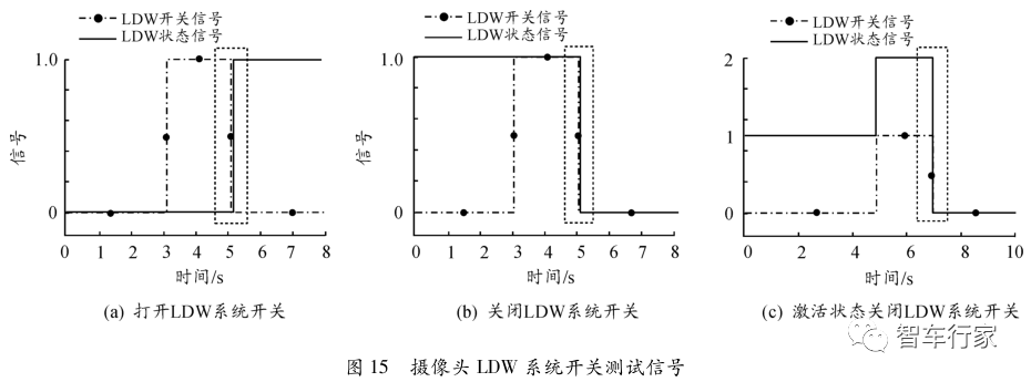
The signal during the test of the LDW system switch is shown in Figure 15. In (a) and (b), the vehicle is in a stationary state, the battery power supply and the engine ignition signal are in the on state, and the LDW system switch signal is a pulse signal, and the falling edge triggers . In (a), the LDW system is in the off state, and the LDW system switch is not turned on. Set the LDW system switch to on, as shown by the change in the dashed box, the LDW state changes to 1, that is, the standby state.
In (b), the LDW system is in the standby state, the LDW system switch is turned on, and the LDW system switch is set to off, and the LDW system state becomes 0, which is the off state. In (c), the vehicle speed is set to 65 km/h, and the LDW system state becomes 2, which is the active state. At this time, the LDW system switch is turned off. .
The test results show that the LDW system switch can meet the requirements and control the state switching of the LDW system. The LDW system activation/exit test result is shown in Figure 16. In (a), when the longitudinal vehicle speed reaches 60 km/h, as shown by the change in the dashed box, the activation state changes suddenly and the LDW system is activated;
In (b), when the longitudinal speed reaches 55 km/h, the activation state changes suddenly, and the LDW system is in the standby state. The test results show that when the vehicle speed changes, although the activation state signal is slightly delayed, the LDW system can automatically activate or deactivate to meet the requirements.

3. 3 Environmental adaptability test
When the environmental adaptability test is performed, the test environment is complicated, and the focus is on verifying the recognition effect of the camera under working conditions such as road surface water, rain, snow, and fog. Among them, when there is water on the road, it is very easy to cause misjudgment of the lane recognition function of the camera, and then seriously interfere with the normal operation of the lane departure warning system.
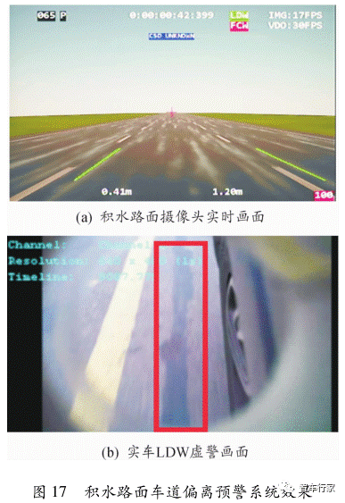
The main manifestation is that the camera mistakenly recognizes stagnant water as a lane, and the lane line recognition jumps more seriously in the entire dynamic test, as shown in Figure 17. Figure 17(a) is the real-time picture of the camera misidentifying the lane line under the condition of road surface water in the loop simulation, and the recognition error is relatively large during the whole test process;
Figure 17(b) is the false alarm situation when the lane departure warning system is tested by the real vehicle, which is consistent with the simulation conditions. In a foggy environment, the camera can still recognize it well, so I don’t need to elaborate. In rainy and snowy weather, it is difficult to simulate the working conditions of rain and snow falling on the camera lens, so focus on when the car is fast or rainy and snowy. The relative movement between the vehicle and the rain and snow causes the falling rain and snow to be approximately in a straight line. Tests were performed with different vehicle speeds and amounts of rain and snow. The results show that there is a small probability of misrecognition, but it is still when the camera is optimized. Considerations.
Concluding remarks
Based on the hardware-in-the-loop simulation platform, the vehicle-mounted camera lane departure warning system is studied in the loop simulation test method. For a mass-produced vehicle-mounted camera, a test case from its basic functional logic to its specific performance is designed, and the simulation test is completed.
In the hardware-in-the-loop test, it is found that lane recognition is prone to loss, false alarm or no alarm when it deviates at a high speed in a bend working condition, especially when driving on a road with water, the lane line recognition jumps Larger, more false alarms, consistent with the data collected by the lane departure system of the actual vehicle, if not optimized in time, it will easily affect the driver’s driving judgment and experience.
The test results prove that the lane departure warning system simulation test method based on the hardware-in-the-loop simulation platform can efficiently, safely and repeatably complete the relevant test verification, and find the shortcomings, provide a reference for the later camera algorithm optimization and the actual vehicle test, which is convenient Find and solve problems faster.
In the further performance test of the camera, although the weather environment of rain, snow and fog is simulated, it cannot effectively simulate the situation when raindrops or snowflakes fall on the camera’s acquisition lens, so this issue will be focused on in the later research. And find a more scientific solution to improve the coverage and fidelity of the simulation test method.
The Links: NL12876BC26-32D MG300M1UK1