Generating stable voltages capable of driving significant quantities of current is one of the fundamental tasks of electronic design. A basic model for a low-voltage electronic circuit goes something like this:
There are various ways to accomplish this. When I first started designing circuits, I used linear voltage regulators—such as the venerable 7805—whenever possible. Nowadays, though, it is impossible to deny that switching regulators are often the superior method, and in my experience, they are usually the superior method.
In this article, we’ll discuss the nomenclature and then explore the basic principles of switching regulation.
“Switching (voltage) regulator” is perhaps the most common and recognizable term for denoting this class of circuit. However, you will also see various combinations of the following terms:
I actually prefer “switch-mode regulator” or “switch-mode power supply,” because “switch-mode” more successfully conveys the nature of these circuits: switching is the mode by which they accomplish their task of regulating or converting voltage.
All of these terms suffer from ambiguity that rarely causes problems but is nonetheless worth noting: “switching regulator” or “switch-mode power supply” could, in theory, refer to a circuit that generates a power rail using switches in conjunction with either an inductor or a capacitor.
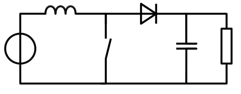
In practice, though, the terms mentioned above are reserved for inductor-based switchers. Figure 1 is an example of an inductor-based switching mode regulator. The vast majority of switch-mode power supplies are inductor-based. These will be the primary focus of this article.

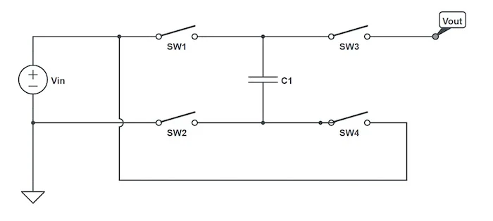
Capacitor-based switchers, such as the example circuit of Figure 2, are typically called “charge-pump” power supplies or “switched-capacitor” power supplies. Figures 1 and 2 are both examples of circuits that produce an output voltage that is higher than the input voltage.

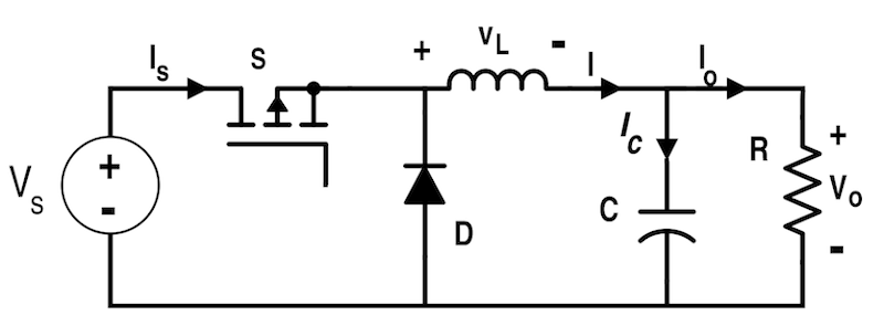
Let’s now think about a linear regulator, as illustrated in Figure 3. Linear regulators can only reduce the voltage, so we know that the input voltage is higher than the output voltage.

A linear regulator requires a small amount of current for operation; this is called the ground current. The ground current is often negligibly small, so let’s ignore it and assume that the current flowing into the regulator is equal to the current flowing out of the regulator and into the powered load circuit.
Now let’s think about power. We calculate electrical power as voltage times current, and since the output has equal current but lower voltage relative to the input, power must be lost somewhere. You can also imagine that the linear regulator is a simple resistive element with a voltage drop:
$$V_{DROP} = V_{IN} – V_{OUT}$$
In this case, the power dissipation of the linear regulator, PREG is:
$$P_{REG} = V_{DROP} \cdot I_{LOAD}$$
One of the components in a linear regulator is, in fact, a switch—not an electromechanical switch, but a transistor that is capable of functioning as a purely electrical switch. However, we don’t call a linear regulator a switching regulator because the switch is not turning on and off; instead, the switch is operating in an intermediate state in which it has a significant resistance, and this resistance dissipates power and allows for a reduction in voltage.
Linear regulation is simple and highly effective, but it is inefficient. The switch is operating in an intermediate, resistive state and dissipates potentially large amounts of power as heat. Unless you want your regulator to function as a regulator and an electric heater, this power is being wasted.
This leads us to the concept of a switch-mode regulator. If we can keep the switch fully on or fully off—in other words, if we can avoid that high-power-dissipation intermediate region—we can create a much more efficient regulator. But our discussion of the linear regulator suggests that the wasted power is necessary for reducing voltage. What to do?
This is where the inductor comes in. An inductor stores and releases energy in such a way that the current through the inductor cannot change instantaneously. On/off switching action leads to an inductor current that gradually increases and decreases. When an inductor is combined with a capacitor, the resulting LC filter can smooth an on/off waveform into a relatively stable voltage. The magnitude of the smoothed-out voltage is determined by the on/off waveform’s duty cycle.
For example, let’s take a look at Figure 4. After filtering, different duty cycles (in this example, 10%, 50%, and 90%) correspond to different DC voltage levels (indicated by the red curves). These DC voltage levels are not perfectly flat because some ripple remains after filtering.

Thus, we can turn the switch on and off at a high frequency and then use pulse-width modulation and filtering to create the desired DC output voltage. We can also monitor a feedback signal and adjust the PWM duty cycle according to load conditions. This is the basic mode of operation in switching regulator circuits: inductive filtering for delivering consistent load current despite on/off switching action; feedback and PWM for regulating the voltage.
Even though the switch is operating at high frequency, it still spends most of its time in the low-power-dissipation states (i.e., the fully on and fully off states). This is why switching regulators can be so much more efficient than linear regulators.
Of course, there are many details and variations that I haven’t mentioned, but if you understand all this, you have a solid foundation for further study.
Figure 5 shows the basic topology of a buck converter, also known as a step-down converter. It uses switch-mode operation to reduce the magnitude of a DC input voltage. (Note that, strictly speaking, this is not a voltage regulator since it does not include the feedback subsystem required to maintain a stable voltage despite variable load conditions.)
